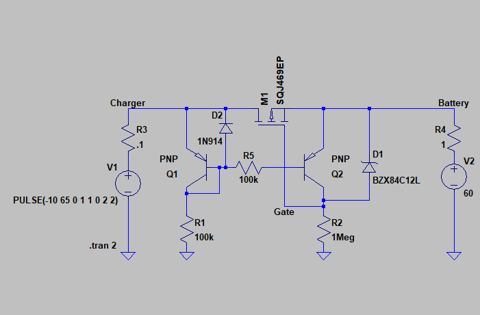
Here’s a circuit for an ideal diode which will handle 60V:
It modifies the basic current mirror of the paired transistors by putting a resistor R5 between them and adding diode D2 to prevent Veb going below -5V on Q1.
Diode D12 keeps the gate voltage on the main MOSFET within specifications. Use a Zener with a voltage around 12-20V.
Resistors R3 and R4 are just simulating the internal resistance of the charger and battery, so the currents don’t become infinite for the simulation. They aren’t part of the ideal diode circuit.
The main MOSFET should be chosen to resist the full reverse voltage (-60V VDS) and have a RDS(on) suitable for the anticipated charge current. This is a pretty demanding specification for a MOSFET: high voltage doesn’t have low resistance. But it should be possible to find one.
The two transistors must be a matched pair, but the exact part numbers aren’t critical. They don’t see the high voltage, so you don’t need any special specification.
The part numbers shown on the schematic are not intended to be recommendations. They were just the first part I found in the standard LTSpice library with the required voltage specifications.