STM32 DAC WaveForm Generator
- Set up a new project as usual with system clock @ 80MHz
- Set up the DAC1 peripheral to work in normal mode with output buffer enabled
- Use the provided MATLAB script to generate lookup tables to be used for this LAB
- Setup timer2 to be the trigger source for DMA1 unit
- Setup DMA1 to move data from memory to DAC peripheral
- Generate a 1KHz sine waveform. Change the lookup table data to make it sawtooth, triangular, sinc functions
And now, let’s build this system step-by-step
Step1: Open CubeMX & Create New Project
Step2: Choose The Target MCU & Double-Click Its Name
STM32L432KC
Step3: Go To The Clock Configuration
Step4: Set The System Clock To Be 80MHz
Step5: Enable The DAC1 Output In Normal Mode & Buffer Enable

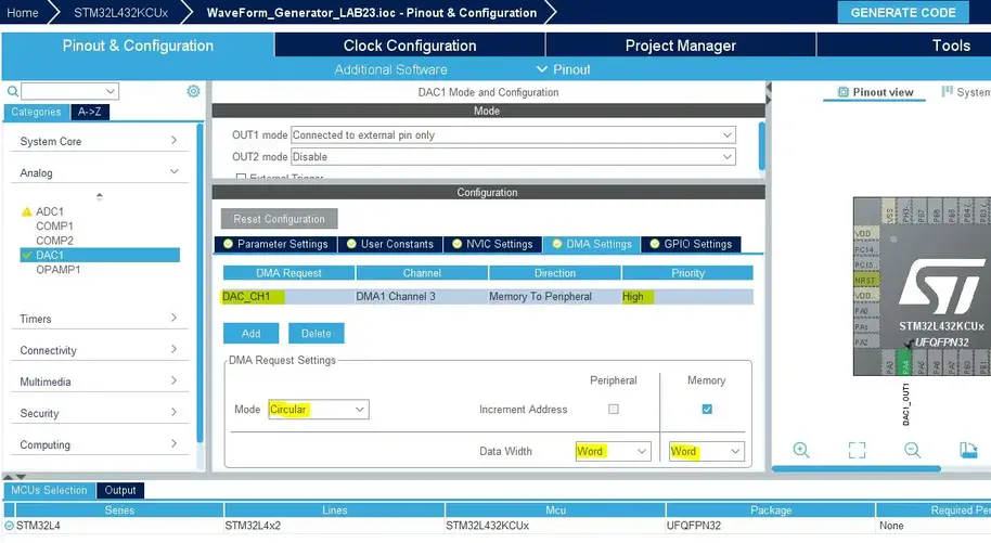
Step6: Enable The DAC1 DMA Channel & Configure It As Shown Below
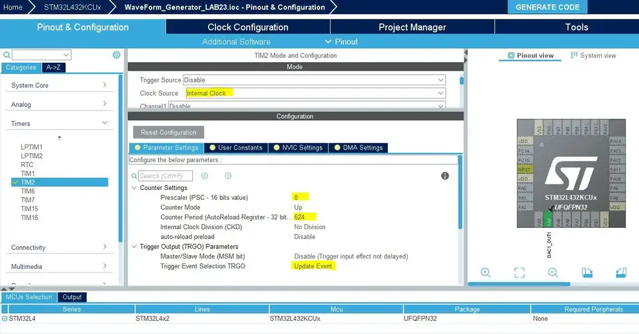
Step7: Now, Configure Timer2 Peripheral As Shown
Do you remember the example of the calculation shown earlier in this article? Where we want to generate a 1kHz sine wave with a system clock of 80MHz and lookup table with 128 entries.
The PCS was chosen to be 0, and the ARR was calculated to be 624. That’s what we’re doing here in this step.
Step8: Generate The Initialization Code & Open The Project In Your IDE
Here is The Application Code For This Demo (main.c)
|
1 2 3 4 5 6 7 8 9 10 11 12 13 14 15 16 17 18 19 20 21 22 23 24 25 26 27 28 29 30 31 32 33 34 35 36 37 38 39 40 41 42 |
#include "main.h" #define NS 128 uint32_t Wave_LUT[NS] = { 2048, 2149, 2250, 2350, 2450, 2549, 2646, 2742, 2837, 2929, 3020, 3108, 3193, 3275, 3355, 3431, 3504, 3574, 3639, 3701, 3759, 3812, 3861, 3906, 3946, 3982, 4013, 4039, 4060, 4076, 4087, 4094, 4095, 4091, 4082, 4069, 4050, 4026, 3998, 3965, 3927, 3884, 3837, 3786, 3730, 3671, 3607, 3539, 3468, 3394, 3316, 3235, 3151, 3064, 2975, 2883, 2790, 2695, 2598, 2500, 2400, 2300, 2199, 2098, 1997, 1896, 1795, 1695, 1595, 1497, 1400, 1305, 1212, 1120, 1031, 944, 860, 779, 701, 627, 556, 488, 424, 365, 309, 258, 211, 168, 130, 97, 69, 45, 26, 13, 4, 0, 1, 8, 19, 35, 56, 82, 113, 149, 189, 234, 283, 336, 394, 456, 521, 591, 664, 740, 820, 902, 987, 1075, 1166, 1258, 1353, 1449, 1546, 1645, 1745, 1845, 1946, 2047 }; DAC_HandleTypeDef hdac1; DMA_HandleTypeDef hdma_dac_ch1; TIM_HandleTypeDef htim2; void SystemClock_Config(void); static void MX_GPIO_Init(void); static void MX_DMA_Init(void); static void MX_DAC1_Init(void); static void MX_TIM2_Init(void); int main(void) { HAL_Init(); SystemClock_Config(); MX_GPIO_Init(); MX_DMA_Init(); MX_DAC1_Init(); MX_TIM2_Init(); HAL_DAC_Start_DMA(&hdac1, DAC_CHANNEL_1, (uint32_t*)Wave_LUT, 128, DAC_ALIGN_12B_R); HAL_TIM_Base_Start(&htim2); while (1) { } } |
The Result For This LAB Testing On My DSO
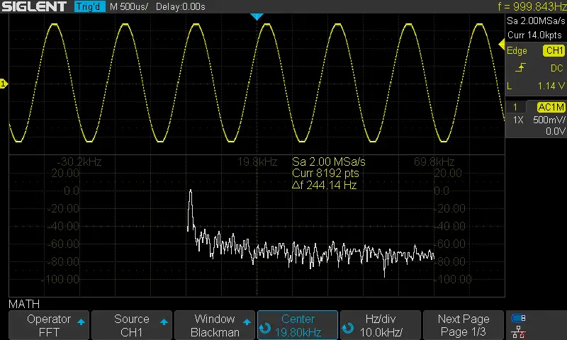
Here is the result for the first test (sine wave @ 1KHz)
The FFT shows a THD of nearly 1 or 2% which is not bad. And can be improved by increasing the sample points and adding an offset so that the signal doesn’t swing to the extreme ends.
Here is the result for the 2nd test (sawtooth wave @ 1KHz)
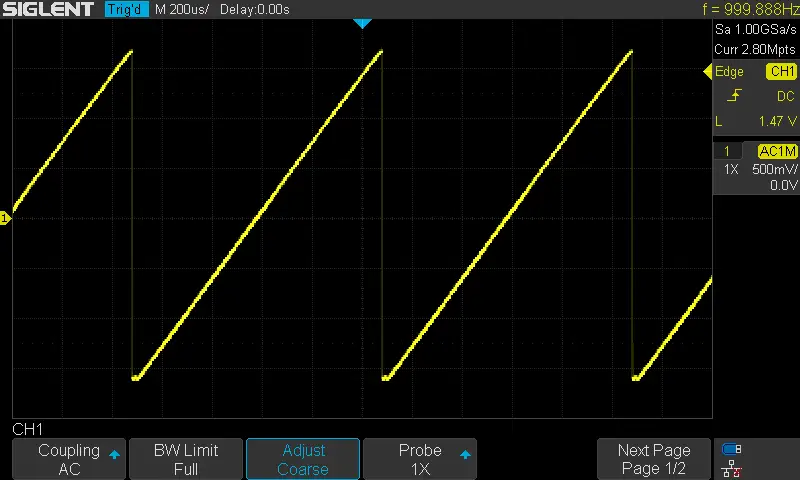
Here is the result for the 3rd test (triangular wave @ 1KHz)
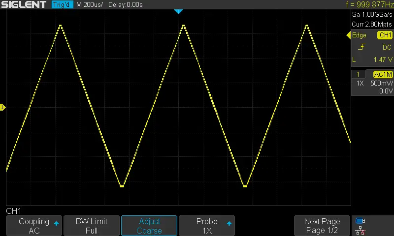
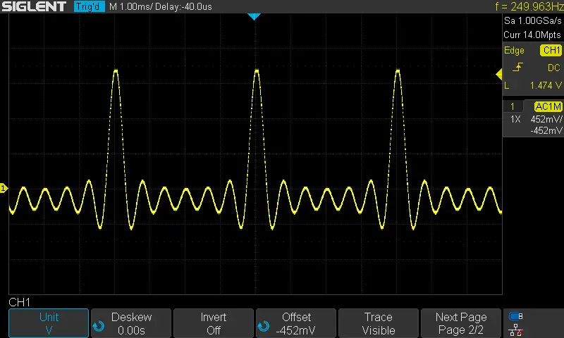
Here is the result for the 4th test “The Beautiful Sinc Function”
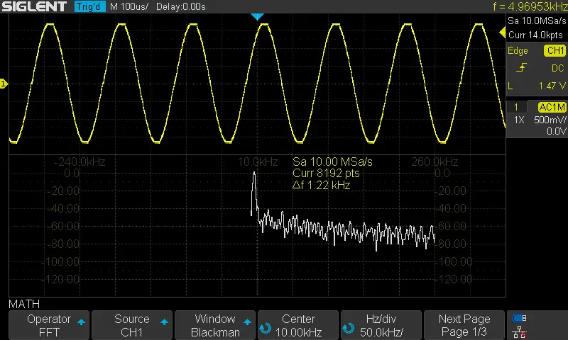
Here is the result for the 5th test (sine wave @ 5KHz)
By writing 125 to the Timer2 ARR, we’d expect the sine output signal’s frequency to increase to 5KHz. And that’s exactly what happens.
