A Little info about the CAN Protocol
I am not going to explain every small detail here, instead we will just focus on some important things. For more details about the Protocol, you can google it.
CAN (Controlled Area Network) Protocol is a way of communication between different devices, but under certain rules. These rules must be followed when a message is transmitted over the CAN bus. Here we are going to see these rules.
Shown below is the Standard CAN Frame
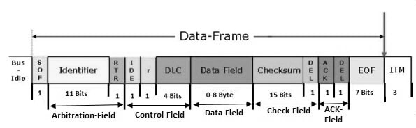
- Here, Identifier is the ID of the transmitting Device
- RTR (Remote Transmission Request) Specifies if the data is Remote frame or Data frame
- IDE specifies if we are using Standard ID or Extended ID
- r is the Reserved bit
- DLC specifies the data length in Bytes
- Data Field is where we can send the data, which should be upto 8 bytes
- Checksum and DEL are the CRC data and it’s Delimiter
- ACK and DEL is the acknowledgment bit and it’s Delimiter
In this Tutorial, we will see upto the Data Field only. The CRC and ACK will be handled by the HAL Library.
Connection and Configuration
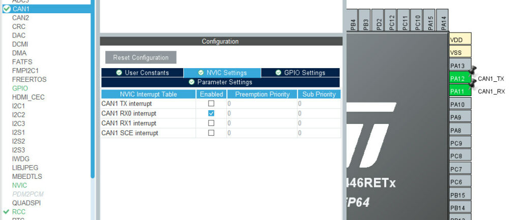
The CubeMX Configuration is as shown below
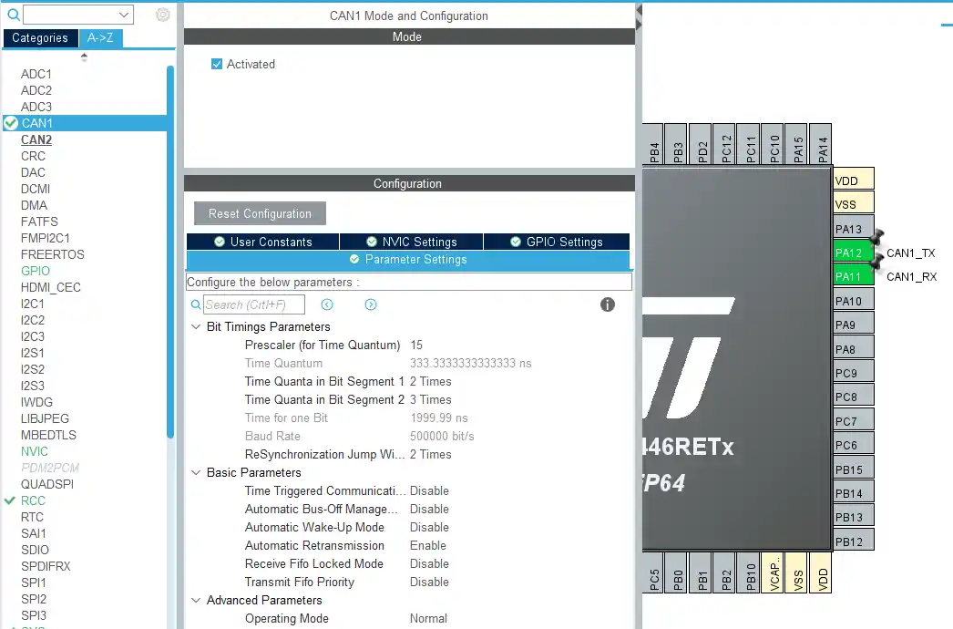
- Here the BAUD RATE is set to 500000 bps. You can try different different combinations for Prescalar and Time Quanta to achieve this.
- The Operating Mode is NORMAL Mode
- Pins PA11 and PA12 are set as CAN_RX and CAN_TX
Update regarding new version of IDE
The Connection between F446 and F103 is shown below.
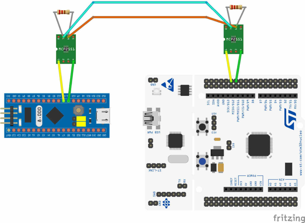
- Here the Tx and Rx from the Transceivers are connected to PA12 and PA11 of the Respective controllers
- CANH and CANL are connected to each other
- Also there is 120 ohms Resistance at each node. This is very important, or else you will not get the data.
How to Modify the CAN Data Frame
To do this, we will define some variable, where we can store the header and the data.
|
1 2 3 4 5 |
CAN_TxHeaderTypeDef TxHeader<span class="token punctuation">;</span> <span class="token class-name">uint8_t</span> TxData<span class="token punctuation">[</span><span class="token number">8</span><span class="token punctuation">]</span><span class="token punctuation">;</span> <span class="token class-name">uint32_t</span> TxMailbox<span class="token punctuation">;</span> |
- Here TxHeader will be used to store the header information, like RTR, DLC, etc. This is type
CAN_TxHeaderTypeDef - TxData is used to store the data, that we are going to transmit over the CAN bus
- TxMailbox is the mailbox, which will be sent to the CAN bus
Now we will store the required values in the TxHeader, and in the TxData.
|
1 2 3 4 5 6 7 |
TxHeader<span class="token punctuation">.</span>IDE <span class="token operator">=</span> CAN_ID_STD<span class="token punctuation">;</span> TxHeader<span class="token punctuation">.</span>StdId <span class="token operator">=</span> <span class="token number">0x446</span><span class="token punctuation">;</span> TxHeader<span class="token punctuation">.</span>RTR <span class="token operator">=</span> CAN_RTR_DATA<span class="token punctuation">;</span> TxHeader<span class="token punctuation">.</span>DLC <span class="token operator">=</span> <span class="token number">2</span><span class="token punctuation">;</span> TxData<span class="token punctuation">[</span><span class="token number">0</span><span class="token punctuation">]</span> <span class="token operator">=</span> <span class="token number">50</span><span class="token punctuation">;</span> TxData<span class="token punctuation">[</span><span class="token number">1</span><span class="token punctuation">]</span> <span class="token operator">=</span> <span class="token number">0xAA</span><span class="token punctuation">;</span> |
- Here CAN_ID_STD means that we are using the Standard ID (not extended)
- 0x446 is the Identifier. This is the ID of the Transmitter, and it should be maximum 11 bit wide
- CAN_RTR_DATA indicates that we are sending a data frame
- DLC is the Length of data bytes, and here we are sending 2 data Bytes
- Now we will store the 2 data bytes in the TxData array
We have the information ready to be transmitted, and now we will finally transmit it on the CAN bus
|
1 2 3 4 |
<span class="token keyword">if</span> <span class="token punctuation">(</span><span class="token function">HAL_CAN_AddTxMessage</span><span class="token punctuation">(</span><span class="token operator">&</span>hcan1<span class="token punctuation">,</span> <span class="token operator">&</span>TxHeader<span class="token punctuation">,</span> TxData<span class="token punctuation">,</span> <span class="token operator">&</span>TxMailbox<span class="token punctuation">)</span> <span class="token operator">!=</span> HAL_OK<span class="token punctuation">)</span> <span class="token punctuation">{</span> <span class="token function">Error_Handler</span> <span class="token punctuation">(</span><span class="token punctuation">)</span><span class="token punctuation">;</span> <span class="token punctuation">}</span> |
This can be done by using HAL_CAN_AddTxMessage. It have the following parameters
- hcan1 is the instance of the CAN, that we are using
- TxHeader is the Header of the message
- TxData is the Data field
- TxMailbox is the mailbox, which will carry the header and data message
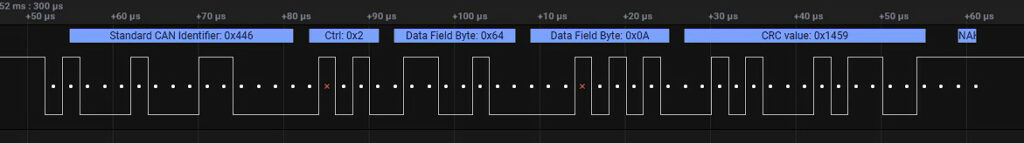
You can see above the data on the TX Line.
- Identifier is 0x446, the STD ID of the transmitter
- Control Field is 0x2, it contains DLC, RTR, IDE
- 2 Bytes of data Field
- And at last there is CRC Value, which was added by the HAL
This message is sent to the CAN bus, and now all the CAN devices on this bus will sort of receive this message. I said sort of, because whether to receive the message or not, depends on the Filter Configuration for each device.
If the message satisfies the conditions as per the FILTER, only then it will be allowed to pass.
Filter Configuration
In order to reduce CPU Load to filter out messages, the STM32 have the Filters built inside the CAN peripheral. Let’s Check them out
|
1 2 3 4 5 6 7 8 9 10 11 12 13 14 |
CAN_FilterTypeDef canfilterconfig<span class="token punctuation">;</span> canfilterconfig<span class="token punctuation">.</span>FilterActivation <span class="token operator">=</span> CAN_FILTER_ENABLE<span class="token punctuation">;</span> canfilterconfig<span class="token punctuation">.</span>FilterBank <span class="token operator">=</span> <span class="token number">18</span><span class="token punctuation">;</span> <span class="token comment">// which filter bank to use from the assigned ones</span> canfilterconfig<span class="token punctuation">.</span>FilterFIFOAssignment <span class="token operator">=</span> CAN_FILTER_FIFO0<span class="token punctuation">;</span> canfilterconfig<span class="token punctuation">.</span>FilterIdHigh <span class="token operator">=</span> <span class="token number">0x446</span><span class="token operator"><<</span><span class="token number">5</span><span class="token punctuation">;</span> canfilterconfig<span class="token punctuation">.</span>FilterIdLow <span class="token operator">=</span> <span class="token number">0</span><span class="token punctuation">;</span> canfilterconfig<span class="token punctuation">.</span>FilterMaskIdHigh <span class="token operator">=</span> <span class="token number">0x446</span><span class="token operator"><<</span><span class="token number">5</span><span class="token punctuation">;</span> canfilterconfig<span class="token punctuation">.</span>FilterMaskIdLow <span class="token operator">=</span> <span class="token number">0x0000</span><span class="token punctuation">;</span> canfilterconfig<span class="token punctuation">.</span>FilterMode <span class="token operator">=</span> CAN_FILTERMODE_IDMASK<span class="token punctuation">;</span> canfilterconfig<span class="token punctuation">.</span>FilterScale <span class="token operator">=</span> CAN_FILTERSCALE_32BIT<span class="token punctuation">;</span> canfilterconfig<span class="token punctuation">.</span>SlaveStartFilterBank <span class="token operator">=</span> <span class="token number">20</span><span class="token punctuation">;</span> <span class="token comment">// how many filters to assign to the CAN1 (master can)</span> <span class="token function">HAL_CAN_ConfigFilter</span><span class="token punctuation">(</span><span class="token operator">&</span>hcan1<span class="token punctuation">,</span> <span class="token operator">&</span>canfilterconfig<span class="token punctuation">)</span><span class="token punctuation">;</span> |
- FilterActivation specifies if we want to enable Filters or not. Obviously we have to enable them
- SlaveStartFilterBank specifies How many Filter Banks do we want to assign to CAN1. Basically the controllers with dual CAN peripheral have 28 Filter Banks, which can be distributed between these 2 CAN. Here I am assigning 20 Filter Banks to the CAN1, and Rest to the CAN 2.
- This parameter is useless for the controllers with single CAN peripheral. And these Controllers have 14 Filter Banks ( 0 to 13)
- FilterBank specifies which Filter Bank do we want to use for the filter Process. Here I have assigned 20 Banks for CAN 1, and I can only choose Out of these 20 Banks. So I am choosing Bank number 18.
- In case of Single CAN Peripheral, you can choose any value between 0 to 13
- FilterFIFOAssignment specifies which FIFO are we going to use for the Receive message. Generally we have 2 FIFOs ( FIFO 0, and FIFO 1). I am choosing FIFO 0
- FilterMode specifies which type of Filter do we want to use. We have 2 types of filters in STM32. MASK MODE, where the Mask register will be used to compare some particular bits in the ID register to the incoming ID. And the LIST MODE, where the incoming ID is directly compared with the ID set in the ID Register.
- I am using MASK Mode here, as It seems to be more useful
- FilterScale specifies If we want to use one 32 bit Filter Register, or 2 16 bit Filter Registers.
- I am using one 32 Bit Register here.
- FilterIdHigh is the Higher 16 Bits of the ID register. The value set in this register will be compared to the incoming Identifier.
- Here I have decided to only compare the STD ID of the incoming message, and that’s why I am shifting the value by 5. The STD ID starts from 5th bit in the ID HIGH Register
- FilterMaskIdHigh is the Higher 16 Bits of the MASK register. The value set in this register will enable the comparison of that particular bit in the ID register to that of the incoming ID.
The Last 2 points might be hard to understand, so I would suggest that you watch the video below. It could be better explained with the working example, and that’s shown in the VIDEO.
Receiving DATA
We will use the interrupt for the RX FIFO, so whenever a message is passed through the Filter an interrupt will be triggered.
First of all We will enable the CAN1 RX0 interrupt in the CubeMX
Now Inside the main Function, we will Activate the Notification for the Received message.
|
1 2 3 4 |
<span class="token keyword">if</span> <span class="token punctuation">(</span><span class="token function">HAL_CAN_ActivateNotification</span><span class="token punctuation">(</span><span class="token operator">&</span>hcan1<span class="token punctuation">,</span> CAN_IT_RX_FIFO0_MSG_PENDING<span class="token punctuation">)</span> <span class="token operator">!=</span> HAL_OK<span class="token punctuation">)</span> <span class="token punctuation">{</span> <span class="token function">Error_Handler</span><span class="token punctuation">(</span><span class="token punctuation">)</span><span class="token punctuation">;</span> <span class="token punctuation">}</span> |
Here we will choose CAN_IT_RX_FIFO0_MSG_PENDING. This would trigger the interrupt, whenever there is some pending message in the RX_FIFO 0. Once the interrupt is triggered, a callback function will be called. In this case, it will be HAL_CAN_RxFifo0MsgPendingCallback
|
1 2 3 4 5 6 7 8 9 10 11 12 13 14 15 16 |
CAN_RxHeaderTypeDef RxHeader<span class="token punctuation">;</span> <span class="token class-name">uint8_t</span> RxData<span class="token punctuation">[</span><span class="token number">8</span><span class="token punctuation">]</span><span class="token punctuation">;</span> <span class="token keyword">void</span> <span class="token function">HAL_CAN_RxFifo0MsgPendingCallback</span><span class="token punctuation">(</span>CAN_HandleTypeDef <span class="token operator">*</span>hcan<span class="token punctuation">)</span> <span class="token punctuation">{</span> <span class="token keyword">if</span> <span class="token punctuation">(</span><span class="token function">HAL_CAN_GetRxMessage</span><span class="token punctuation">(</span>hcan<span class="token punctuation">,</span> CAN_RX_FIFO0<span class="token punctuation">,</span> <span class="token operator">&</span>RxHeader<span class="token punctuation">,</span> RxData<span class="token punctuation">)</span> <span class="token operator">!=</span> HAL_OK<span class="token punctuation">)</span> <span class="token punctuation">{</span> <span class="token function">Error_Handler</span><span class="token punctuation">(</span><span class="token punctuation">)</span><span class="token punctuation">;</span> <span class="token punctuation">}</span> <span class="token keyword">if</span> <span class="token punctuation">(</span><span class="token punctuation">(</span>RxHeader<span class="token punctuation">.</span>StdId <span class="token operator">==</span> <span class="token number">0x103</span><span class="token punctuation">)</span><span class="token punctuation">)</span> <span class="token punctuation">{</span> datacheck <span class="token operator">=</span> <span class="token number">1</span><span class="token punctuation">;</span> <span class="token punctuation">}</span> <span class="token punctuation">}</span> |
- Here we will Receive the message from RX_FIFO 0.
- The message Header will be stored in the RxHeader, and the data will be stored in RxData.
- We can do further checks, like if the message was received from the ID 0x103, then the datacheck flag will be set.
- Later in the while loop we can perform some actions based on this flag
|
1 2 3 4 |
<span class="token keyword">if</span> <span class="token punctuation">(</span>datacheck<span class="token punctuation">)</span> <span class="token punctuation">{</span> <span class="token function">HAL_GPIO_WritePin</span><span class="token punctuation">(</span>GPIOA<span class="token punctuation">,</span> GPIO_PIN_5<span class="token punctuation">,</span> GPIO_PIN_SET<span class="token punctuation">)</span><span class="token punctuation">;</span> <span class="token punctuation">}</span> |
For example, If the Flag is set, The LED will turn ON.