Using Direct Memory Access (DMA) in STM32 projects
In many microcontroller projects, you need to read and write data. It can read data from the peripheral unit like ADC and write values to RAM. In another case, maybe you need to send chunks of data using SPI. Again you need to read it from RAM and continuously write to the SPI data register. When you do this using processor – you lose a significant amount of processing time. Most advanced microcontrollers have a Direct Memory Access (DMA) controller to avoid occupying the CPU. As its name says – DMA does data transfers between memory locations without the need for a CPU.

Low and medium-density ST32 microcontrollers have a single 7-channel DMA unit, while high-density devices have two DMA controllers with 12 independent channels. In STM32VLDiscovery, their ST32F100RB microcontroller with a single DMA unit having 7 channels.
DMA controller can do automated memory-to-memory data transfers, also do peripheral to memory and peripheral-to-peripheral. DMA channels can be assigned one of four priority levels: very high, high, medium, and low. And if two same priority channels are requested simultaneously – the lowest number of the channel gets priority. DMA channel can be configured to transfer data into the circular buffer. So DMA is an ideal solution for any peripheral data stream.
Programming DMA controller
Simply speaking, programming DMA is relatively easy. Each channel can be controlled using four registers: Memory address, peripheral address, number of data, and configuration. And all channels have two dedicated registers: DMA interrupts the status register and interrupts the clear flag register. Once set, DMA takes care of memory address increment without disturbing the CPU. DMA channels can generate three interrupts: transfer finished, half-finished, and transfer error.
As an example, let’s write a simple program that transfers data between two arrays. Let’s do the same task using DMA and without it to make it more exciting. Then we can compare the time taken in both cases.
Here is a code of DMA memory to memory transfer:
|
1 |
#include "stm32f10x.h" #include "leds.h" #define ARRAYSIZE 800 volatile uint32_t status = 0; volatile uint32_t i; int main(void) { //initialize source and destination arrays uint32_t source[ARRAYSIZE]; uint32_t destination[ARRAYSIZE]; //initialize array for (i=0; i<ARRAYSIZE;i++) source[i]=i; //initialize led LEDsInit(); //enable DMA1 clock RCC_AHBPeriphClockCmd(RCC_AHBPeriph_DMA1, ENABLE); //create DMA structure DMA_InitTypeDef DMA_InitStructure; //reset DMA1 channe1 to default values; DMA_DeInit(DMA1_Channel1); //channel will be used for memory to memory transfer DMA_InitStructure.DMA_M2M = DMA_M2M_Enable; //setting normal mode (non circular) DMA_InitStructure.DMA_Mode = DMA_Mode_Normal; //medium priority DMA_InitStructure.DMA_Priority = DMA_Priority_Medium; //source and destination data size word=32bit DMA_InitStructure.DMA_PeripheralDataSize = DMA_PeripheralDataSize_Word; DMA_InitStructure.DMA_MemoryDataSize = DMA_MemoryDataSize_Word; //automatic memory increment enable. Destination and source DMA_InitStructure.DMA_MemoryInc = DMA_MemoryInc_Enable; DMA_InitStructure.DMA_PeripheralInc = DMA_PeripheralInc_Enable; //Location assigned to peripheral register will be source DMA_InitStructure.DMA_DIR = DMA_DIR_PeripheralSRC; //chunk of data to be transfered DMA_InitStructure.DMA_BufferSize = ARRAYSIZE; //source and destination start addresses DMA_InitStructure.DMA_PeripheralBaseAddr = (uint32_t)source; DMA_InitStructure.DMA_MemoryBaseAddr = (uint32_t)destination; //send values to DMA registers DMA_Init(DMA1_Channel1, &DMA_InitStructure); // Enable DMA1 Channel Transfer Complete interrupt DMA_ITConfig(DMA1_Channel1, DMA_IT_TC, ENABLE); NVIC_InitTypeDef NVIC_InitStructure; //Enable DMA1 channel IRQ Channel */ NVIC_InitStructure.NVIC_IRQChannel = DMA1_Channel1_IRQn; NVIC_InitStructure.NVIC_IRQChannelPreemptionPriority = 0; NVIC_InitStructure.NVIC_IRQChannelSubPriority = 0; NVIC_InitStructure.NVIC_IRQChannelCmd = ENABLE; NVIC_Init(&NVIC_InitStructure); //LED on before the transfer LEDToggle(LEDG); //Enable DMA1 Channel transfer DMA_Cmd(DMA1_Channel1, ENABLE); while(status==0) {}; LEDToggle(LEDB); for (i=0; i<ARRAYSIZE;i++) { destination[i]=source[i]; } LEDToggle(LEDB); while (1) { //interrupts does the job } } |
First of all, we create two arrays: source and destination. The size of the length is determined by ARRAYSIZE, which in our example is equal to 800
We use the LED library from the previous tutorial – they indicate a start and stop-transfer for both modes – DMA and CPU. As we see in the code, we must turn on the DMA1 clock to make it functional. Then we start loading settings into DMA_InitStructure. For this example, we selected DMA1 Channel1, so first of all, we call DMA_DeInit(DMA1_Channel1) function, ensuring DMA is reset to its default values. Then turn on memory to memory mode, then we select normal DMA mode (also, we could select circular buffer mode). As priority mode, we assign Medium. Then we choose the data size to be transferred (32-bit word). This needs to be done for both – peripheral and memory addresses.
NOTE! If one of the memory sizes would be different, say source 32-bit and destination 8- bit – then DMA would cycle four times in 8-bit chunks.
Then we load destination, source start addresses, and the amount of data to be sent. Afterload these values using DMA_Init(DMA_Channel1, &DMA_InitStructure). After this operation, DMA is prepared to do transfers. Any time DMA can be fired using DMA_Cmd(DMA_Channel1, ENABLE) command.
To catch the end of DMA transfer, we initialized DMA transfer Complete on channel1 interrupt.
|
1 |
NVIC_InitTypeDef NVIC_InitStructure; //Enable DMA1 channel IRQ Channel */ NVIC_InitStructure.NVIC_IRQChannel = DMA1_Channel1_IRQn; NVIC_InitStructure.NVIC_IRQChannelPreemptionPriority = 0; NVIC_InitStructure.NVIC_IRQChannelSubPriority = 0; NVIC_InitStructure.NVIC_IRQChannelCmd = ENABLE; NVIC_Init(&NVIC_InitStructure); |
Where we could toggle the LED and change the status flag giving a signal to start the CPU transfer test.
|
1 |
void DMA1_Channel1_IRQHandler(void) { //Test on DMA1 Channel1 Transfer Complete interrupt if(DMA_GetITStatus(DMA1_IT_TC1)) { status=1; LEDToggle(LEDG); //Clear DMA1 Channel1 Half Transfer, Transfer Complete and Global interrupt pending bits DMA_ClearITPendingBit(DMA1_IT_GL1); } } |
CPU-based memory copy routine is simple:
|
1 |
//wait for DMA transfer to be finished while(status==0) {}; LEDToggle(LEDB); for (i=0; i<ARRAYSIZE;i++) { destination[i]=source[i]; } LEDToggle(LEDB); |
Measuring DMA and CPU-based transfer speeds
Since LEDG is connected to GPIOC pin 9 and LEDB is connected to GPIOC pin 8, we could track start and end pulses using scope:
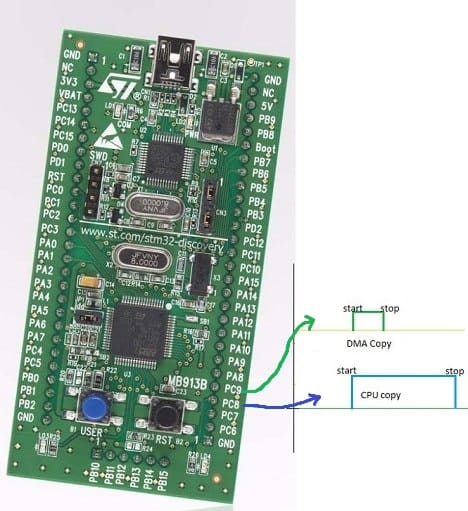
So using 800 32-bit word transfer using DMA took 214μs:

While using the CPU memory copy algorithm, it took 544μs:

This shows a significant increase in data transfer speed (more than two times). And with DMA most considerable benefit is that the CPU is unoccupied during transfer and may do other intense tasks or go into sleep mode.
I hope this example gives an idea of DMA’s importance. We can do loads of work with DMA on the hardware level. We will get back to it when we get to other STM32 features like ADC.